Thermal Energy Storage: Part 2 — Innovative Thermal Energy Storage Technologies
- Andreas Zemelka
One More Innovative TES Concept
There are many thermal energy storage (TES) technologies:
- using waste heat or electrical power as the heat source
- designed for short- or long-duration storage
- covering high- or low-temperature heat demand
- using different materials as the heat storage medium (e.g., water, molten salt, molten aluminium, steel, sand, crushed rock or concrete)
- designed for small-scale applications, such as residential heating, or for industrial applications.
Some technologies exist primarily as concepts, others have reached prototype or pilot-plant stage, while some are already in commercial operation. Many TES technologies are still relatively new, and long-term operating experience remains important for identifying opportunities for further modification and improvement.
Companies, research organisations and inventors continue to explore new approaches and concepts. I have also been working on my own TES concept.
Without revealing too many details, the concept can be briefly described as “high-temperature thermal energy storage based on a granular storage medium and conductive heating.”
The TES is charged with electrical power, for example low-cost or surplus renewable electricity, which is converted into heat. The thermal energy is then stored in a granular storage medium, such as sand. When required, the stored heat can be extracted through a heat exchanger and transferred to a suitable process medium, such as steam, hot air or thermal oil.
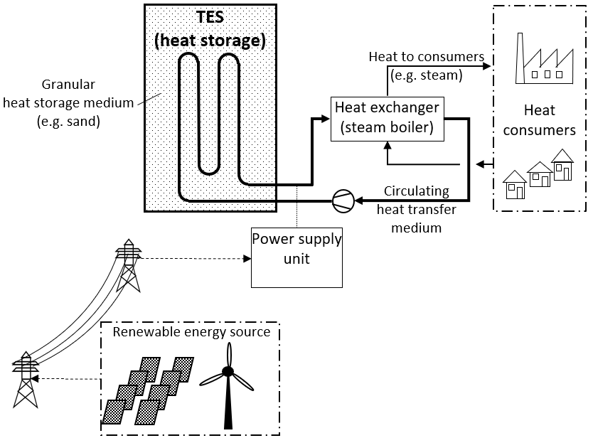
This TES can have various configurations (e.g., cuboid, cylindrical or containerised) and can be arranged horizontally or vertically. The system can be scaled according to the required storage capacity, from a few MWh to the GWh range, either by increasing the size of the TES reservoir or by deploying multiple smaller TES units.
The system is particularly well suited to applications covering the daily thermal energy demand of a process (daily cycling). However, longer storage durations of several days or potentially weeks are also possible, depending on the application and system design.
Depending on the materials used, particularly for the heating elements and internal piping, the maximum temperature of the storage medium can reach approximately 800°C or potentially higher. The temperature profile within the storage medium varies according to the state of charge (SOC). The concept is particularly suitable for supplying thermal processes requiring temperatures of up to approximately 400°C and, depending on the specific design, potentially up to 500°C.
For a better understanding of the operating principle, the following simplified working characteristics are based on an illustrative example with the following assumptions:
| TES effective thermal storage capacity: | 25 MWh |
| TES charging capacity: | 10 MW |
| One complete process cycle: | 24 hours |
| Maximum temperature of the heat storage medium: | 800°C |
| Continuous process heat demand: | approx. 1 MW at 300°C |
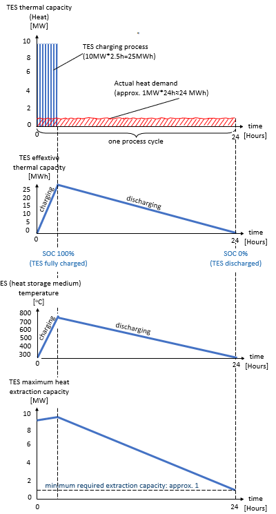
In this particular example, the TES cycles between two temperatures, 300°C and 800°C (ΔT = 500°C).
Based on the mass and specific heat capacity of the storage medium, these two temperatures—the upper and lower operating temperatures—determine the effective thermal storage capacity, Q, of the TES:
Q = m × c × ΔT
where:
- Q = effective thermal storage capacity
- m = mass of the heat storage medium
- c = specific heat capacity of the heat storage medium
- ΔT = temperature difference between the upper and lower operating temperatures
This represents the thermal energy that can be extracted from the TES and supplied to a thermal process.
The discharging phase is shown in the diagram above as a straight line for simplification. In an actual application, the discharge profile would follow the thermal demand of the process. Furthermore, charging and discharging can take place simultaneously. In such a case, the TES can supply a total amount of thermal energy over a given period (e.g., 24 hours) that exceeds its nominal thermal storage capacity.
Main Advantages:
- Low complexity, robust design and simple operation, with no moving parts within the storage system
- Reliable and potentially cost-effective supply of low-carbon thermal energy
- Potential for relatively low CAPEX and OPEX due to the simple system configuration
- Applicable to residential heating as well as industrial processes requiring temperatures of up to approximately 400°C and, depending on the design, potentially up to 500°C
- Potentially high electricity-to-useful-heat efficiency
- As a flexible electricity consumer, the TES can potentially generate additional revenue through participation in demand-response, balancing or other electricity flexibility markets (more on this subject in subsequent articles)
- In addition to its primary function of supplying heat, the TES can support the integration of renewable energy and contribute to the stabilization of electricity grids (more on this subject in subsequent articles)
- The TES can also be combined with a steam turbine generator to convert stored thermal energy back into electricity, following a principle similar to that used in concentrated solar power (CSP) plants.
Possible applications will be discussed in the next article.